A cold compass for the specifier
Cull your tools and steady your gaze: this is a practical framework for hardware specifiers to probe inverter manufacturers on four‑quadrant active and reactive power control latency. The ledger below pairs dark clarity with concrete tests so procurement never trusts rhetoric alone. If you design at the rack or system level, weave this into your energy storage system design process—start there as your north star: energy storage system design.

Core pillars of the audit
Build the audit on four pillars: deterministic latency, control topology transparency, test reproducibility, and field performance traces. Each pillar demands measurable evidence, not promises. For deterministic latency, ask for microsecond‑level loop timing logs; for control topology, request architecture diagrams showing where active power and reactive power loops intersect. Reproducibility means vendor-supplied test scripts and a hardware-in-the-loop snapshot. Field traces should include sampled waveforms of voltage, current, and power factor during a grid event—those are the cold proof.
Testing latency in four‑quadrant control
Define tests that isolate command-to-action latency. Use a stepped active-power injection while simultaneously commanding reactive-power setpoints; record the control loop response and communication hop times. Measure: control loop period, I/O ADC latency, DSP execution time, and network jitter. Include a static-load and dynamic-load scenario—both must pass. Don’t accept averaged numbers only. Demand time-stamped traces that show worst-case latency under CPU and communication stress. Real terms: inverter latency, four‑quadrant control, control loop. —This will expose buried jitter that marketing glosses over.
Protocol, telemetry, and firmware hygiene
Probe the communication stack and telemetry cadence. Ask for message schemas, buffer sizes, and failover behaviors. Check whether the inverter supports deterministic protocols or depends on best-effort messaging that bloats under congestion. Firmware must be versioned with release notes that map fixes to latency regressions. Require a changelog that ties firmware commits to measured control performance—no opaque blobs. Include a checkpoint: ensure remote diagnostics can extract raw loop data for at least 30 days post‑event.
Common manufacturer pitfalls and practical alternatives
Manufacturers often conflate stability margins with latency headroom—mistaking damping for speed. Others deliver single‑point performance graphs rather than worst-case behavior. When this happens, consider alternatives: vendors with modular control cards that allow field swap, or suppliers offering edge‑localized controllers that take control of four‑quadrant handling away from congested CENTRAL CPUs. Compare architectures: tight integrated inverters versus modular energy storage system designs where control responsibilities are explicitly partitioned. Favored are systems that provide hardware-in-the-loop validation kits and open telemetry.
Real-world anchor: why this matters now
Grid operators have faced sharp solar ramps and reactive demands—California’s documented “duck curve” remains a sober lesson: rapid changes in active generation force simultaneous reactive swings. Systems that mask latency collapse during those ramps. Field reports from large-scale projects near Los Angeles show that only inverters with repeatable loop timing sustained stable volt‑VAR behavior. That practical history underpins why your audits must demand measured traces and why modular deployments often survive where monoliths fail. Link this to procurement by requiring on-site acceptance tests tied to your site profile and to the modular energy storage system designs you plan to deploy: modular energy storage system designs.
Golden rules for specification and selection
Adopt three critical evaluation metrics as your final bar:
1) Worst‑case command‑to‑effect latency (ms) measured under CPU and network stress, not averages;
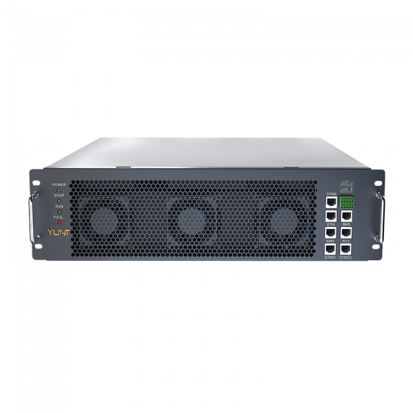
2) Proven four‑quadrant control resilience, demonstrated by end-to-end time‑stamped waveform traces during a rapid active‑power ramp; and
3) Firmware and telemetry transparency—change logs that map code changes to quantified latency performance and an available HIL kit for reproducible acceptance tests.
These rules convert dark uncertainty into auditable facts. They sharpen vendor discussions and make installer acceptance meaningful.
Trust hinges on evidence—collect it, test it, demand it. YUNT. —Finished.